Logic gates are the building blocks of digital systems. Every digital device—from simple calculators to powerful computers—relies on these fundamental components to perform operations and make decisions based on binary inputs.
In this tutorial, you will learn what logic gates are, how they work, the different types of logic gates, along with their truth tables, symbols, and practical applications.
What are Logic Gates?
Logic gates are electronic circuits that perform logical operations on one or more binary inputs to produce a single binary output. These logic gates operate based on Boolean algebra, where inputs and outputs are represented as either HIGH (1) or LOW (0).
Each logic gate follows a specific rule or logic to determine the output. For example, some gates produce an output only when all inputs are HIGH, while others may produce an output when any one of the inputs is HIGH.
Logic gates are implemented using electronic components such as transistors and diodes. They are the fundamental units used in digital circuit design. Every digital circuit, such as adders, multiplexers, memory units, and processors, is built by stacking multiple logic gates together.
To understand a logic gate, we look at both the Boolean expression and the truth table for each gate. A Boolean expression is a mathematical representation of the logic performed by the gate, written using variables such as A and B. Using this expression, you can determine the output for a given set of inputs.
A truth table lists all possible input combinations along with their corresponding outputs. It helps you quickly understand how a particular logic gate responds to different input conditions, making it easier to visualize and verify the gate’s behavior.
Types of Logic Gates
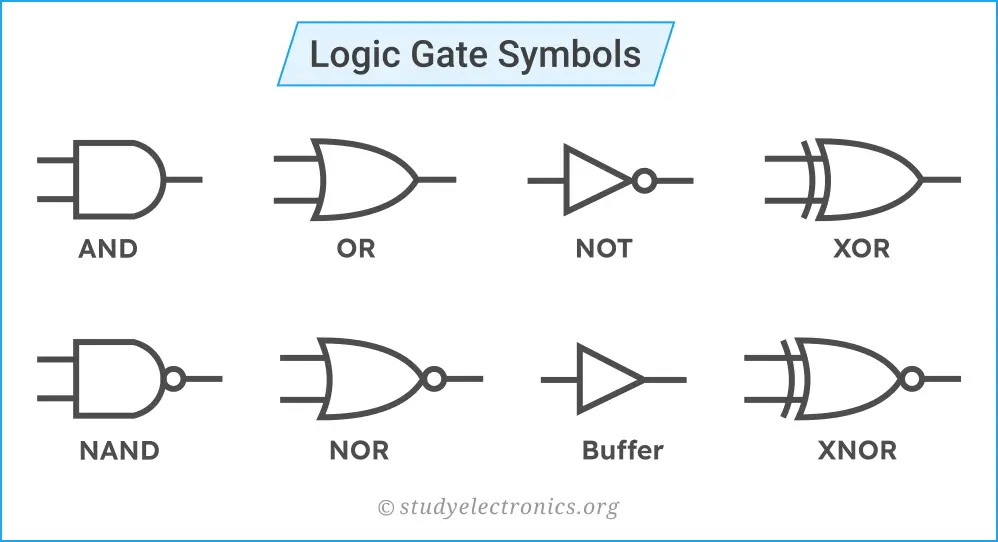
There are 7 logic gates: AND, OR, NOT, NAND, NOR, XOR, and XNOR. They are grouped into three categories based on their function.
Basic Logic Gates
AND, OR, and NOT gates are basic (or primary) logic gates. They are the foundation of any digital logic. These gates represent the basic operations of Boolean algebra: the AND gate performs multiplication-like operations, the OR gate performs addition-like operations, and the NOT gate performs inversion (complement).
Any complex logic function can be built using these basic gates. That means all other gates, such as NAND, NOR, XOR, and XNOR, are derived from them or can be expressed using their logic.
Universal Logic Gates
NAND and NOR gates are universal logic gates. A single type of these logic gates (either NAND or NOR) is enough to implement any Boolean expression or digital circuit. That’s why they are called universal logic gates.
For example, a NAND gate can be used to create NOT, AND, and OR gates. Similarly, a NOR gate can also be used to create NOT, OR, and AND gates.
These gates are important in digital electronics because they simplify circuit design and reduce the need for multiple types of ICs. They are widely used in practical digital electronics and chip design.
Special Logic Gates
XOR (Exclusive OR) and XNOR (Exclusive NOR) gates are special logic gates. They are designed for specific operations such as comparison and error detection, parity generation, and arithmetic operations in digital circuits.
AND Gate
The AND gate is one of the basic logic gates used in digital electronics. It performs a logical multiplication operation on its inputs. It takes two or more inputs and produces one output.
An AND gate gives a HIGH (1) output only when all of its inputs are HIGH (1). If any one of the inputs is LOW (0), the output will be LOW (0). This means the output is true only when all conditions are satisfied.

For a two-input AND gate with inputs A and B, the Boolean expression is written as:
\(\text{Output : } Y=A.B\)
The Boolean symbol for the AND operation is a dot (·), which can also be omitted and written simply as AB. In programming languages (C and similar), the AND operation is represented using the “&” operator, for example: Y = A & B;.
You can also understand the behaviour of an AND gate using the truth table shown above. From the truth table, you can see that the output is HIGH only when both inputs are HIGH.
In real-world applications, the AND gate is used in situations where multiple conditions must be satisfied at the same time. For example, a system should turn ON only when all the switches are pressed.
Properties of the AND Gate
Important properties of an AND gate are given below.
- Performs logical AND (logical multiplication) operation.
- It can take two or more inputs and produce one output.
- Output is HIGH when all inputs are HIGH; otherwise, it is LOW.
OR Gate
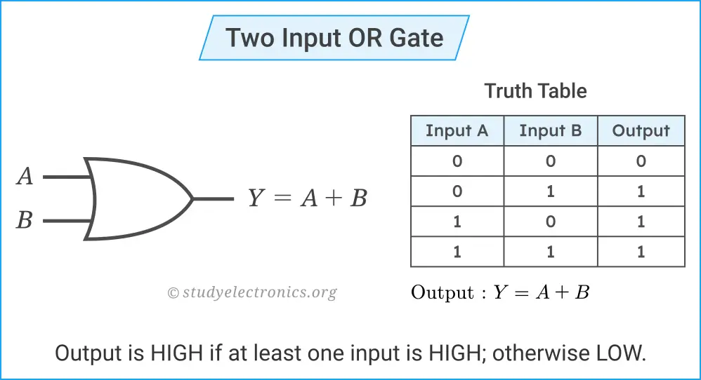
The OR gate is one of the basic (primary) logic gates used in digital electronics. It performs a logical addition operation on its inputs. It takes two or more inputs and produces one output.
An OR gate gives a HIGH (1) output if at least one of its inputs is HIGH (1). The output becomes LOW (0) only when all inputs are LOW (0). This means the output is true if any one of the input conditions is satisfied.
For a two-input OR gate with inputs A and B, the Boolean expression is written as:
\(\text{Output : }Y=A+B\)
The Boolean symbol for the OR operation is “+”. In programming languages (C and similar), the OR operation is represented using the “|” operator, for example: Y = A | B;.
You can also understand the behaviour of an OR gate using the truth table shown above. From the truth table, you can see that the output is HIGH whenever at least one input is HIGH.
In real-world applications, the OR gate is used in situations where any one of multiple input conditions is satisfied. For example, a system turns ON if either of two switches is pressed.
Properties of the OR Gate
The main properties of the OR gate are as follows.
- Performs logical OR (logical addition) operation.
- It takes two or more inputs and produces one output.
- Output is HIGH if at least one input is HIGH; otherwise, it is LOW.
NOT Gate
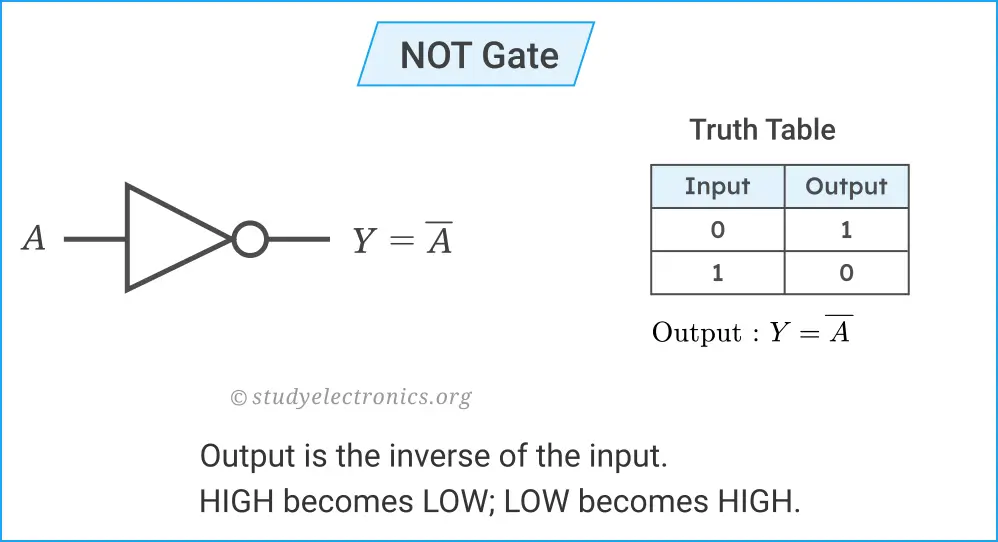
The NOT gate is also a basic (primary) logic gate. It performs a logical inversion operation on its input. The NOT gate takes only one input and produces one output.
The NOT gate produces an output that is the opposite (complement) of the input. If the input is HIGH (1), the output becomes LOW (0), and if the input is LOW (0), the output becomes HIGH (1).
For a NOT gate with input A, the Boolean expression is written as:
\(\text{Output : }Y=\overline{A} \text{ or } A^\prime\)
The Boolean symbol for the NOT operation is a bar over the variable or a prime symbol (′). In programming languages (C and similar), the NOT operation is represented using the “~” operator, for example: Y = ~ A;.
From the above truth table, you can also see that the output is always the inverse of the input.
In real-world applications, the NOT gate is used wherever a signal needs to be reversed or complemented. For example, it is commonly used in control systems where an action must occur when a condition is NOT satisfied.
Properties of the NOT Gate
The NOT gate has the following important properties.
- Has only one input and one output.
- Output is the inverse (complement) of the input.
NAND Gate
The NAND gate is a universal logic gate formed by combining an AND gate followed by a NOT gate. It performs the inverse of the AND operation. It first performs the AND operation and then inverts the result. You can remember it as the NOT of AND.
The NAND gate takes two or more inputs and produces one output. It gives a LOW (0) output only when all of its inputs are HIGH (1). For all other input combinations, the output is HIGH (1). This means it is exactly opposite to the AND gate.
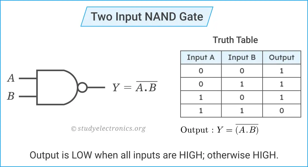
For a two-input NAND gate with inputs A and B, the Boolean expression is written as:
\(\text{Output : }Y=\overline{(A.B)}\)
You can also understand the behaviour of an NAND gate using the truth table shown above. From the truth table, you can see that the output is LOW only when both inputs are HIGH.
The NAND gate is called a universal logic gate because it can be used to implement all other logic gates, including AND, OR, and NOT. Due to this property, NAND gates are widely used in digital circuit design and integrated circuits.
In real-world applications, NAND gates are commonly used in memory circuits, control systems, and various digital logic designs where flexibility and simplicity are required.
Properties of the NAND Gate
The NAND gate has the following properties.
- Takes two or more inputs and produces one output.
- Output is LOW when all inputs are HIGH; otherwise, it is LOW.
NOR Gate
The NOR gate is a universal logic gate formed by combining an OR gate followed by a NOT gate. It performs the inverse of the OR operation. It first performs the OR operation and then inverts the result. You can remember it as the NOT of OR.
The NOR gate takes two or more inputs and produces one output. It gives a HIGH (1) output only when all of its inputs are LOW (0). For all other input combinations, the output is LOW (0). This means it is exactly opposite to the OR gate.
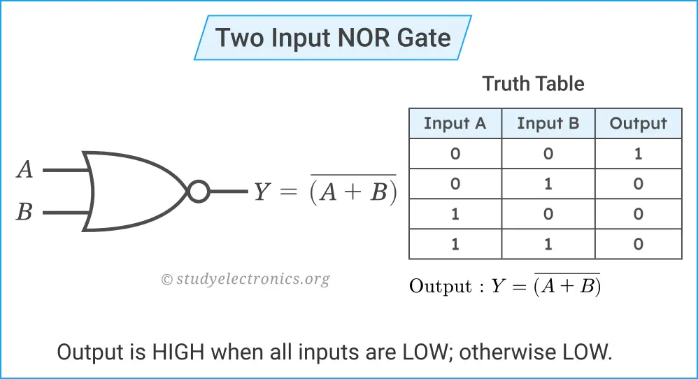
For a two-input NOR gate with inputs A and B, the Boolean expression is written as:
\(\text{Output : }Y=\overline{(A+B)}\)
You can also understand the behaviour of an NOR gate using the truth table shown above. From the truth table, you can see that the output is HIGH only when both inputs are LOW.
The NOR gate is called a universal logic gate because it can be used to implement all other logic gates, including AND, OR, and NOT. Due to this property, NOR gates are widely used in digital circuit design and integrated circuits.
In real-world applications, NOR gates are used in control logic, memory circuits, and digital systems where a condition must be true only when all inputs are false.
Properties of the NOR Gate
The properties of the NOR gate are as follows.
Properties of the NOR gates are
- Takes two or more inputs and produces one output.
- Output is HIGH when all inputs are LOW; otherwise, LOW.
Exclusive OR Gate (XOR)
The XOR gate is a special logic gate used in digital electronics. It performs a comparison operation between its inputs. A single XOR gate takes only two inputs, but a three or multi-input XOR operation can be implemented using multiple two-input XOR gates.
An XOR gate gives a HIGH (1) output only when the inputs are different. If both inputs are the same (both 0 or both 1), the output is LOW (0). This means the output is HIGH when exactly one input is HIGH.
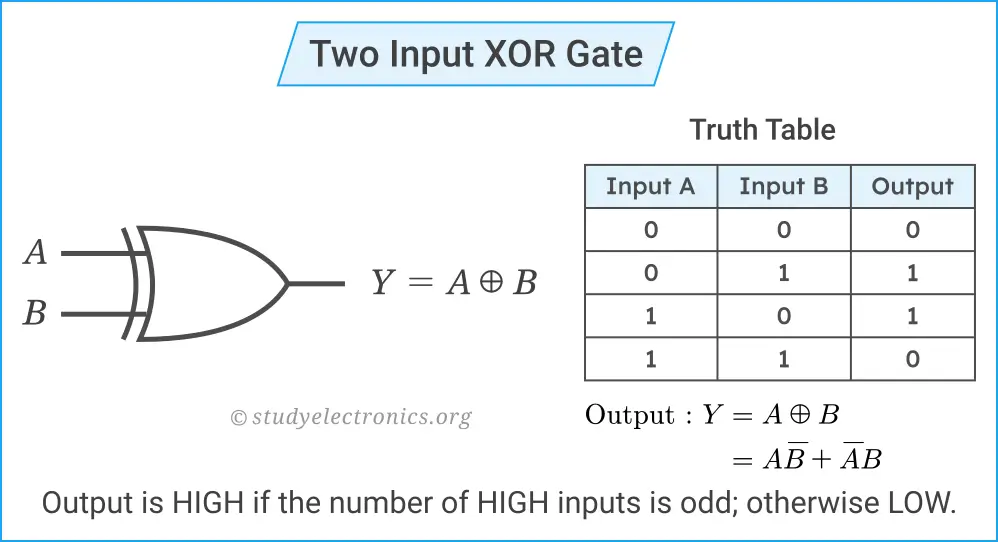
For a two-input XOR gate with inputs A and B, the Boolean expression is written as:
\(\text{Output : }Y=A\oplus B\)
It can also be expressed using basic gates as:
\( Y=A\overline{B}+\overline{A}B\)
The Boolean symbol for the XOR is \(\oplus\). In programming languages (C and similar), the XOR operation is represented using the “^” operator, for example: Y = A ^ B;.
You can also understand the behaviour of an XOR gate using the truth table shown above. From the truth table, you can see that the output is HIGH only when the inputs are different.
In real-world applications, the XOR gate is widely used in arithmetic circuits such as adders, where it is used to generate the sum output. It is also used in comparison circuits, error detection, and parity generation.
Properties of the XOR Gate
The XOR gate has the following key properties.
- The XOR gate takes only two inputs.
- Output is HIGH only if one input is HIGH; otherwise, it is LOW.
Exclusive NOR Gate (XNOR)
The XNOR (Exclusive NOR) gate is a special logic gate used in digital electronics. It is built using the combination of an XOR gate followed by a NOT gate. It performs the XOR operation first, then complements the result. In simple words, the XNOR gate is the complement of the XOR gate.
The XNOR gate also takes only two inputs, but a three or multiple-input XNOR operation could be performed using multiple two-input XNOR gates.
An XNOR gate gives a HIGH (1) output only when both inputs are the same. If the inputs are different, the output is LOW (0). This means the output is true when both inputs are equal.
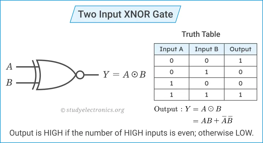
For a two-input XNOR gate with inputs A and B, the Boolean expression is written as:
\(\text{Output : }Y=A\odot B\)
It can also be expressed using basic gates as:
\(Y=AB+\overline{A} \text{ }\overline{B}\)
The boolean symbol for the XNOR operation is \(\odot\). In programming languages (C and similar), the XNOR operation is expressed as: Y = ~(A ^ B);.
You can also understand the behaviour of an XNOR gate using the truth table shown above. From the truth table, it is clear that the output is HIGH only when the inputs are the same.
In real-world applications, the XNOR gate is widely used in digital comparators, error detection and checking systems, and parity checking circuits.
Properties of the XNOR Gate
The following are the key properties of the XNOR gate.
- The XNOR gate also takes only two inputs.
- Output is HIGH when the inputs are similar; otherwise, it is LOW.
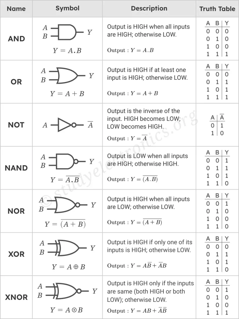
Logic Gate with Symbols, Boolean Expressions, and Truth Tables