In the previous article, you learned that a diode allows current to flow in only one direction. Now, we will use this principle to build a rectifier circuit that converts an AC signal into a DC signal—specifically, a half-wave rectifier.
In this tutorial, you will learn the working principle of a half-wave rectifier, its circuit diagram, input and output waveforms, important parameters such as average voltage, RMS value, ripple factor, efficiency, and its advantages and disadvantages.
What is a Half-Wave Rectifier?
A rectifier is an electronic circuit that converts AC (Alternating Current) into DC (Direct Current). Half-wave rectifiers are the simplest type of rectifier. It allows only one half of each complete sine wave of the AC signal (either the positive or the negative half-cycle) to pass through and blocks the other half.
The input supply may be single-phase or multi-phase, but in every case, the circuit conducts during only one half of each cycle. It is called a half-wave rectifier because it passes only one half of the AC waveform.
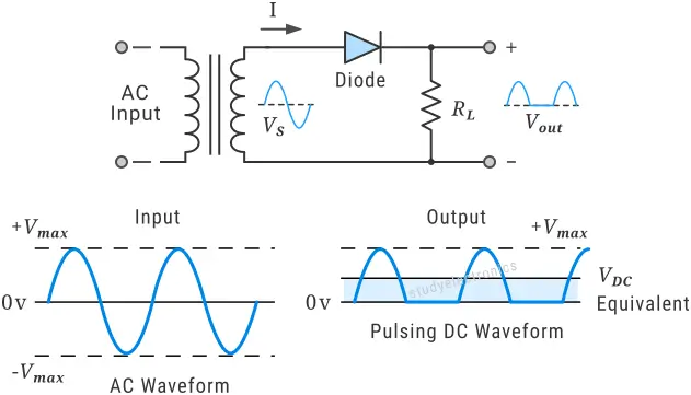
In the image below, you can see a simple half-wave rectifier along with its corresponding input and output waveforms.
A rectifier circuit uses a diode as its main component because of its unidirectional property. For low-current applications (typically less than 1 A), a small-signal diode can be used.
However, if the circuit requires higher forward current or higher reverse voltage blocking capability, a small-signal diode may overheat and eventually fail. In such high-power applications, a power diode should be used instead. For low-voltage, high-frequency rectifier applications, Schottky diodes are preferred due to their fast switching speed and low forward voltage drop.
The 1N400x series is one of the most commonly used diode series for rectifier circuits. These diodes are rated for about 1 A forward current, with reverse voltage ratings starting from 50 V in the 1N4001 and increasing up to 1000 V in the 1N4007.
Half Wave vs Full Wave Rectifier
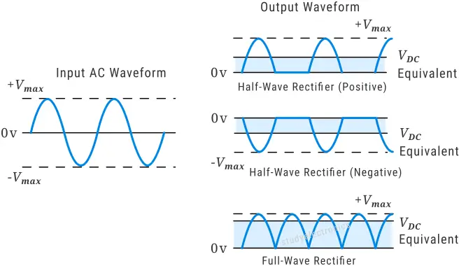
A half-wave rectifier passes only one half of the AC signal and outputs zero volts during the other half-cycle. In contrast, a full-wave rectifier uses both halves of the AC signal, converting the negative half-cycle into a positive one.
A full-wave rectifier provides higher efficiency and a lower ripple factor compared to a half-wave rectifier, because it utilizes the entire input waveform.
In the image below, you can see the difference between the output waveforms of a half-wave rectifier and a full-wave rectifier.
Half-Wave Rectifier Circuit
A half-wave rectifier uses only one diode. When an alternating current (AC) is applied, the diode conducts during one half-cycle and blocks the other half-cycle. By reversing the direction of the diode, we can choose which half of the AC waveform is allowed to pass.
Thus, there are two types of half-wave rectifiers: Positive half-wave rectifier and Negative half-wave rectifier.
Positive Half Rectifier
The circuit consists of a single diode connected in series with a load resistor across an alternating current (AC) supply. The output voltage is taken across the load resistor.
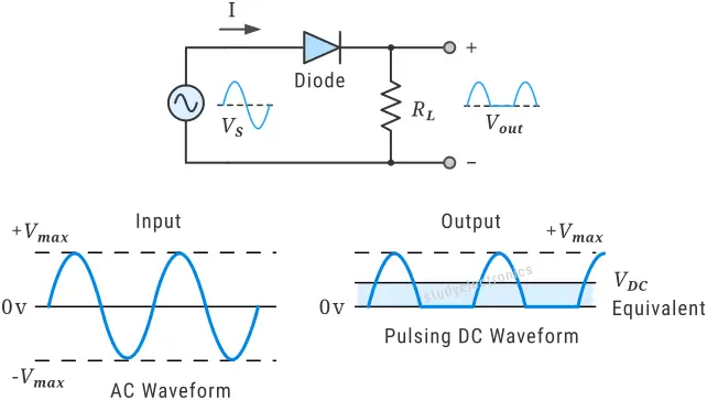
During the positive half-cycle, the diode becomes forward-biased and allows current to flow through the load. During the negative half-cycle, the diode is reverse-biased and blocks current, resulting in a pulsating DC output.
Negative Half Rectifier
A negative half-wave rectifier also uses a single diode connected in series with a load resistor across an AC supply, but the diode is reversed compared to the positive half-wave configuration.
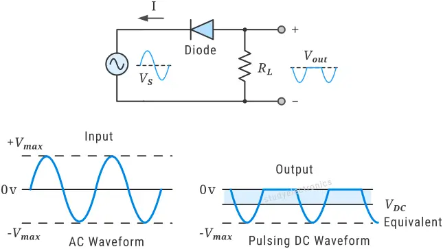
During the negative half-cycle of the AC input, the diode becomes forward-biased and conducts, allowing current to flow through the load resistor. During the positive half-cycle, the diode is reverse-biased and blocks current. As a result, the output across the load consists only of negative half-cycles of the input waveform, producing a pulsating negative DC voltage.
Half-wave Rectifier with Smoothing Capacitor
The ripple voltage in a simple half-wave rectifier can be reduced by adding a capacitor filter. The diode is in series with the load resistor, just like a normal half-wave rectifier. A capacitor is placed in parallel with the load resistor, and the output is taken across the load. The capacitor acts as a filter, smoothing the pulsating DC output.
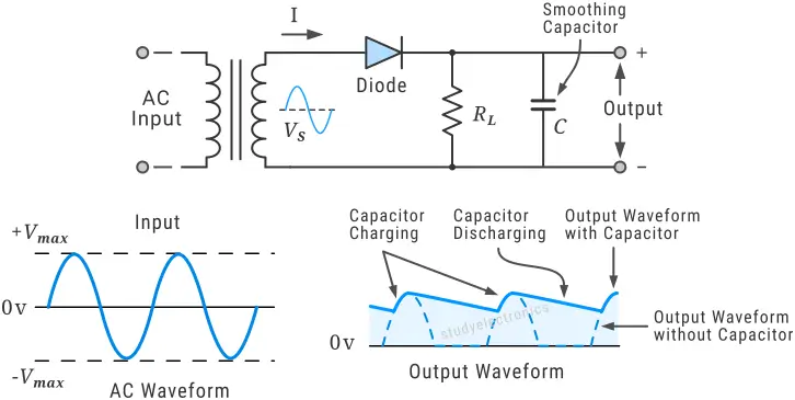
During the positive half-cycle, the diode conducts and charges the capacitor up to the peak voltage. When the input voltage starts decreasing, or during the negative half-cycle, the diode becomes reverse-biased, but the capacitor discharges slowly through the load resistor. This discharge maintains the output voltage instead of letting it fall to zero, thereby filling the gaps between pulses. As a result, the ripple is reduced, and the output becomes smoother DC.
Output Parameters of Half-Wave Rectifier
Average (DC) Output Voltage
The average DC output voltage is the average value of the rectifier’s output waveform over one complete cycle. Since the output of a half-wave rectifier is pulsating DC (only one half of the AC waveform appears at the output), we calculate the average value over a full 360° cycle.
For a half-wave rectifier with peak voltage :
Where,
- Vm = Peak value of the input voltage
- VDC = Average (DC) value of the output voltage
RMS Output Voltage
The RMS (Root Mean Square) output voltage represents the effective value of the rectifier’s output voltage. It tells us how much DC voltage would produce the same heating effect in a resistor as the pulsating output waveform.
For a half-wave rectifier with peak voltage :
RMS Output Current
The RMS (Root Mean Square) output current represents the effective value of the load current. It is the value of DC current that would produce the same effect in the load resistor as the pulsating output current.
For a half-wave rectifier, the RMS output current is:
Efficiency of a Half-Wave Rectifier
The efficiency of a rectifier is determined by the ratio of DC output power delivered to the load and the AC input power supplied to the rectifier.
For a Half-Wave Rectifier DC Output Power is:
and AC Input Power is
So, the efficiency for a half-wave rectifier is,
Ripple Factor
The ripple factor (γ) indicates the amount of AC component (ripple) present in the rectifier output relative to its DC component.
It is defined as:
For a half-wave rectifier, the ripple factor is:
\begin{array}{l} \gamma = \sqrt{ (\frac{ V_{rms}}{ V_{dc}}) ^ {2} – 1} \end{array}Substituting the RMS and DC values into the equation and simplifying, we obtain , which indicates a high ripple content in the output.
Form factor
The form factor is defined as the ratio of the RMS value to the average (DC) value of the output waveform.
A higher form factor indicates more ripple in the output waveform. The form factor of a half-wave rectifier is approximately 1.57, while the form factor of a full-wave rectifier is approximately 1.11, indicating that the full-wave rectifier has less ripple and a smoother output.
Summary
In practice, the half-wave rectifier is rarely used because of its major disadvantages. The output amplitude is much lower than the input peak voltage, and there is no output during one half of the AC cycle, meaning half of the input power is wasted. The resulting output is pulsating DC with excessive ripple, making it unsuitable for most practical applications.
To overcome these limitations, a full-wave rectifier is used in most cases, as it provides higher efficiency and a smoother DC output.